Welcome!

By registering with us, you'll be able to discuss, share and private message with other members of our community.

SignUp Now!

Write-Up: Boost Gauge Install (TRD S/C)

rat7761

Member
Joined
Jul 28, 2008
Messages
563
Reaction score
2
boostgauge.jpg


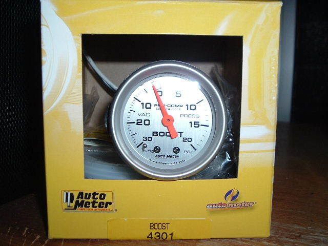
Autometer 2 1/16" Ultralite boost gauge.

boostgaueinstall11.jpg


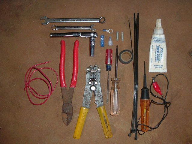
Here are the tools you'll need. I won't describe them all. If you're reading this, you should know exactly what everything is.

boostgauge10.jpg


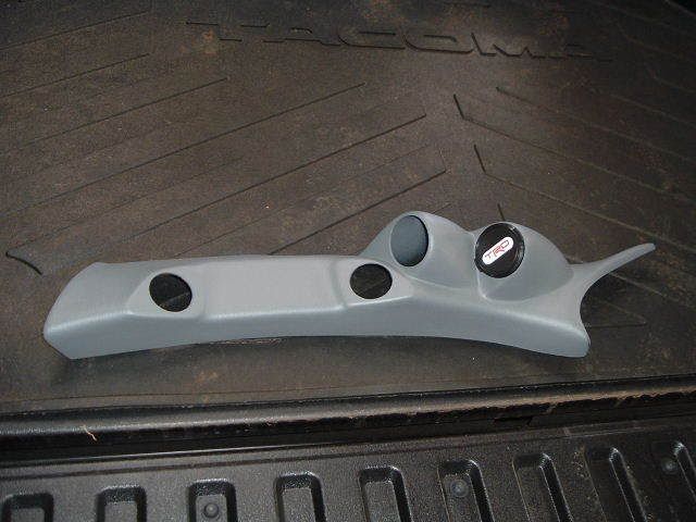
This is a Lotek dual gauge pod. www.gaugepods.com

boostgaugeinstall.jpg


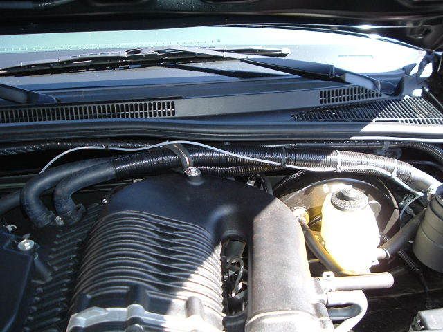
Run the plastic boost line that came with the boost gauge through the hood latch cable grommet. No need to drill extra holes in the firewall. Feed it from the engine compartment and...

boostgaugeinstall2.jpg


...Pull it through from the driver's compartment.

boostgaugeinstall6.jpg


I zip tied the boost line to one of the heat exchanger coolant hoses.

boostgaugeinstall1.jpg


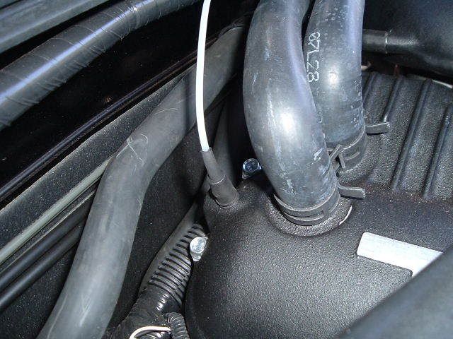
And used the rubber fitting that came with the boost gauge to connect it to the boost port on the blower.

boostgaugeinstall7.jpg


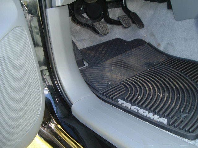
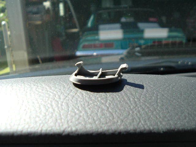
Pop off the rocker panel trim by hand.

boostgaugeinstall4.jpg


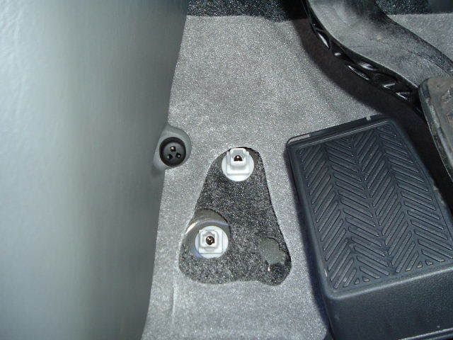
Pop the footrest off by hand also. Unscrew the black nut and pull the kick panel trim off towards the rear of the truck.

boostgaugeinstall5.jpg


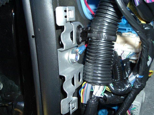
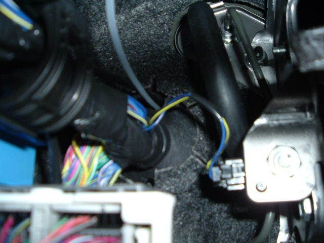
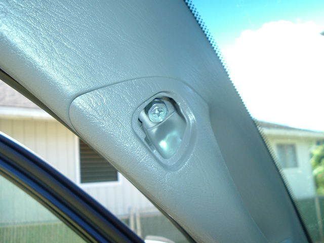
Now you can use a ring terminal and use the bolt in the pic as the ground for the gauge light.

boostgaugeinstall3.jpg


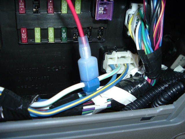
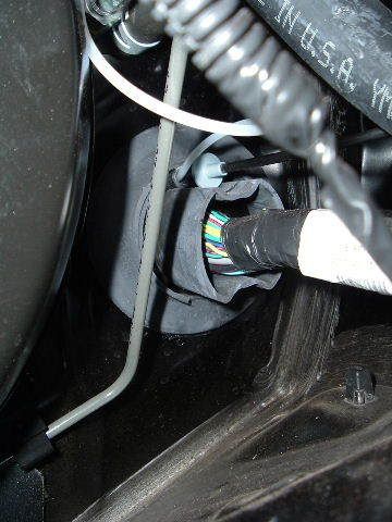
I back probed this white/aqua wire that is behind the coin holder with a test light and used a wire tap and male spade for the switched 12V power. This wire gets power when the key is turned to the ACC position. Since the instrument panel lights are always on, I figured the gauge light can always be on too.

boostgaugeinstall8.jpg


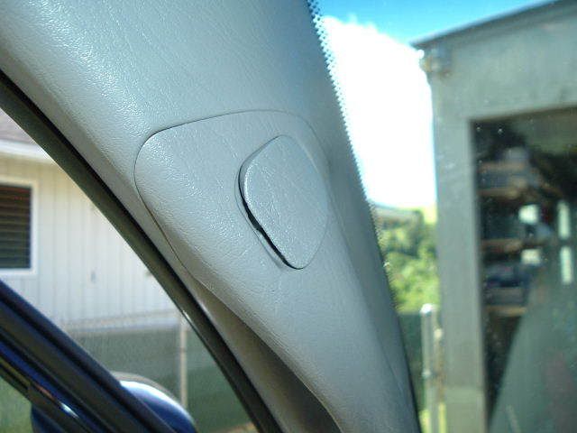
Next, pop off the grab handle covers from the bottom with a small flathead wrapped with electrical tape.

boostgaugeinstall10.jpg


The side on the left is the side you pop the cover off from. There is a tab on the other side.

boostgaugeinstall9.jpg


Unscrew the two screws and pull the grab handle off. Remove the A-pillar trim from the top first.

boostgauge11.jpg


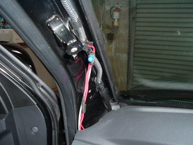
Run the wires up to the pillar. There is no need to remove any other panels. Once the coin holder and A-pillar trim are removed, there is a clear shot all the way up to the pillar.

boostgaugeinstll11.jpg


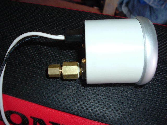
Use teflon sealant on the large fitting to the boost gauge. The compression fitting that attaches the line to the gauge is self sealing.

boostgauge14.jpg


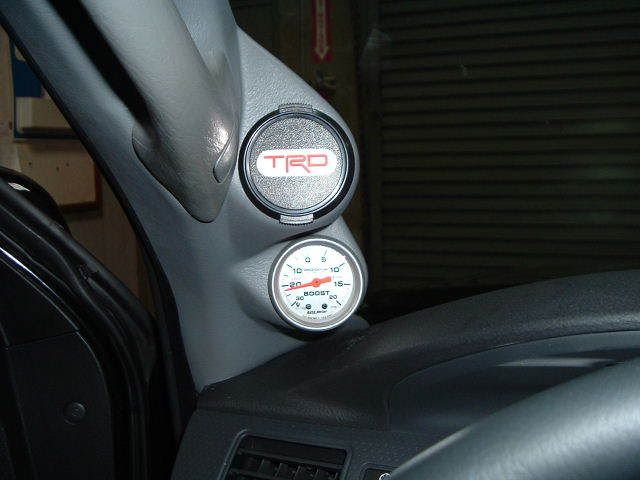
The Lotek pod just replaces the original A-pillar trim piece. The grab handle bolts hold the pod in place. I needed to enlarge the grab handle holes in the pod with a file to make it fit right. Make your power and ground connections with butt connectors and install the boost line to the gauge with the supplied compression fitting. The gauge is a press fit into the pod so just push it in. I got a Lotek block off plate for the extra space I'm saving for a wideband later. Now take a test drive and try to keep your eyes on the road.
 
Last edited:

kishxrs

New Member
Joined
May 26, 2008
Messages
21
Reaction score
0
nice....very thorough. how fast is that 69 camaro in the garage?
 

rat7761

Member
Joined
Jul 28, 2008
Messages
563
Reaction score
2
11.70 @ 115 MPH all motor on drag radials. 11.00 @ 123 MPH on the bottle.
 

5H4D0WD347H

New Member
Joined
Apr 24, 2007
Messages
10,450
Reaction score
0
Nice install man, looks good!

I am going to add a few since this is a write up.

For guys that have gauges utilizing electric senders (MAP sensor) here are some pictures:

mapmount3.jpg


mapmount4.jpg


mapmount5.jpg


The tubing for the MAP was ran behind the wiring harness out of site to the reference port on the supercharger.

The bracket was fabbed from some aluminum, hardware, and a sticker.

The sender wires are ran through the loom shown in the picture, through the passenger side grommet. The loom continues to follow the wires on the other side behind the glove box and underneath the dashboard to the gauge.
 
Last edited:

Tapp

New Member
Joined
May 2, 2007
Messages
4,383
Reaction score
0
looks good,an awesome write up!!!

that Camaro looks BADASS!
 

zrgray

New Member
Joined
Mar 8, 2009
Messages
237
Reaction score
0
Nice write up, look forward to doing this. Did the pod come with that plug if you aren't using the 2nd opening, or did you get that somewhere else?
 

zrgray

New Member
Joined
Mar 8, 2009
Messages
237
Reaction score
0
Finally did this yesterday along with a wideband, very helpful!
 

Sproulesxrunner

Active Member
Joined
May 11, 2010
Messages
3,278
Reaction score
2
Nice install man, looks good!

I am going to add a few since this is a write up.

For guys that have gauges utilizing electric senders (MAP sensor) here are some pictures:

mapmount3.jpg


mapmount4.jpg


mapmount5.jpg


The tubing for the MAP was ran behind the wiring harness out of site to the reference port on the supercharger.

The bracket was fabbed from some aluminum, hardware, and a sticker.

The sender wires are ran through the loom shown in the picture, through the passenger side grommet. The loom continues to follow the wires on the other side behind the glove box and underneath the dashboard to the gauge.

I have the TRD boost gauge and I don't think it came with a Map sensor. Would the install be the exact same as the OPs write up?
 

lamia2super

Member
Joined
Jan 27, 2013
Messages
647
Reaction score
0
nice write up ! i was wondering if you knew where i could get that little rubber fitting
 

STONER-X

Active Member
Joined
May 15, 2008
Messages
3,372
Reaction score
1
Autozone in the help section..... it will be in a multi package
 

lamia2super

Member
Joined
Jan 27, 2013
Messages
647
Reaction score
0
Autozone in the help section..... it will be in a multi package

They were no help but I did manage to find one hiding in the vacuum section. I got my Trd gauge up and running now I'm planning to swap out the bulbs inside the gauge to LEDs.
 
Top Bottom